Replacing the rubber shutter button on the folding Polaroid SLR is a relatively simple task, but does require some procedures to be followed sequentially in order to ensure success. In some cases, special tools and/or precautions may be required in order to affect this change.
Please read these steps carefully before attempting to replace the shutter button.
This guide is meant as a general tutorial for this procedure and Retrospekt takes no responsibility for any damage or mishaps that may occur during an at-home repair attempt.
If you would like us to replace the button for you, please contact us at
Pola_studio@163.com
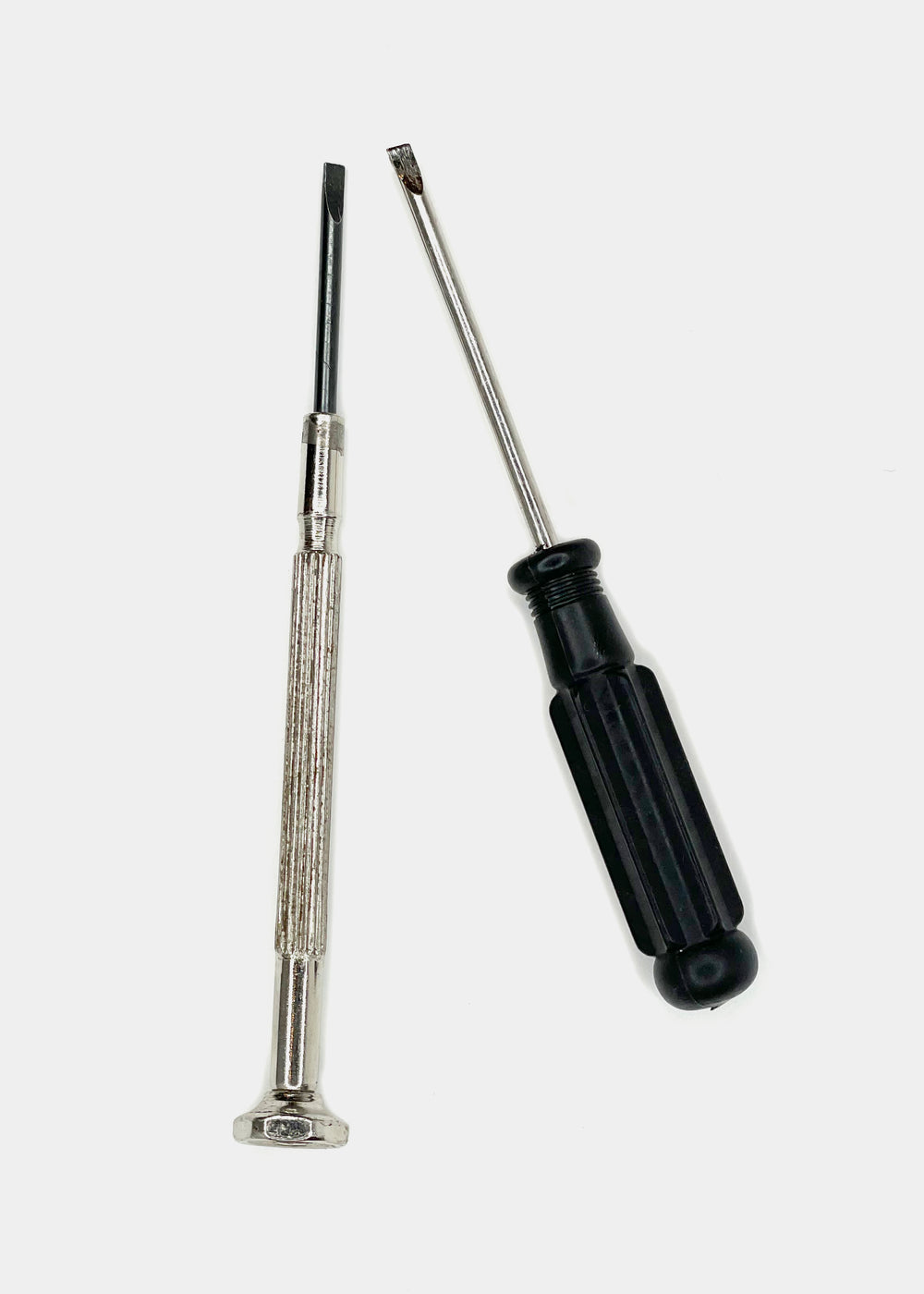

- A flat bladed jewelers screwdriver — we recommend a 1.5mm, but anything between 1.2-2mm will work
- Your new shutter button
Some cameras may require additional tools owing to the need of additional disassembly. Those tools will be specified in the sections where they are specifically required.
IDENTIFY YOUR CAMERA MODEL
If your camera is a manual focus model that has a black, plastic shutter crate, you can continue to the basic procedure section.
If your camera is a manual focus model and has a silver/aluminum shutter crate, it is very likely that there are two internal fasteners securing the shutter cover to the shutter crate. If when following the basic procedure the shutter cover cannot be easily removed, additional disassembly is required. Please proceed to the section regarding additional disassembly.

If your camera is an autofocus model with the gold circular sonar (Sonar, SLR 680, Polaroid 690, etc), please follow the additional instructions found in the autofocus section.
BASIC PROCEDURE
REMOVING THE SHUTTER COVER
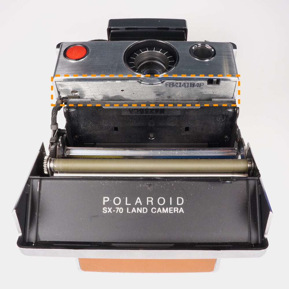
Except on earlier cameras (please see later section in this document), access to the shutter button securement is easily accessed by removing the shutter cover.
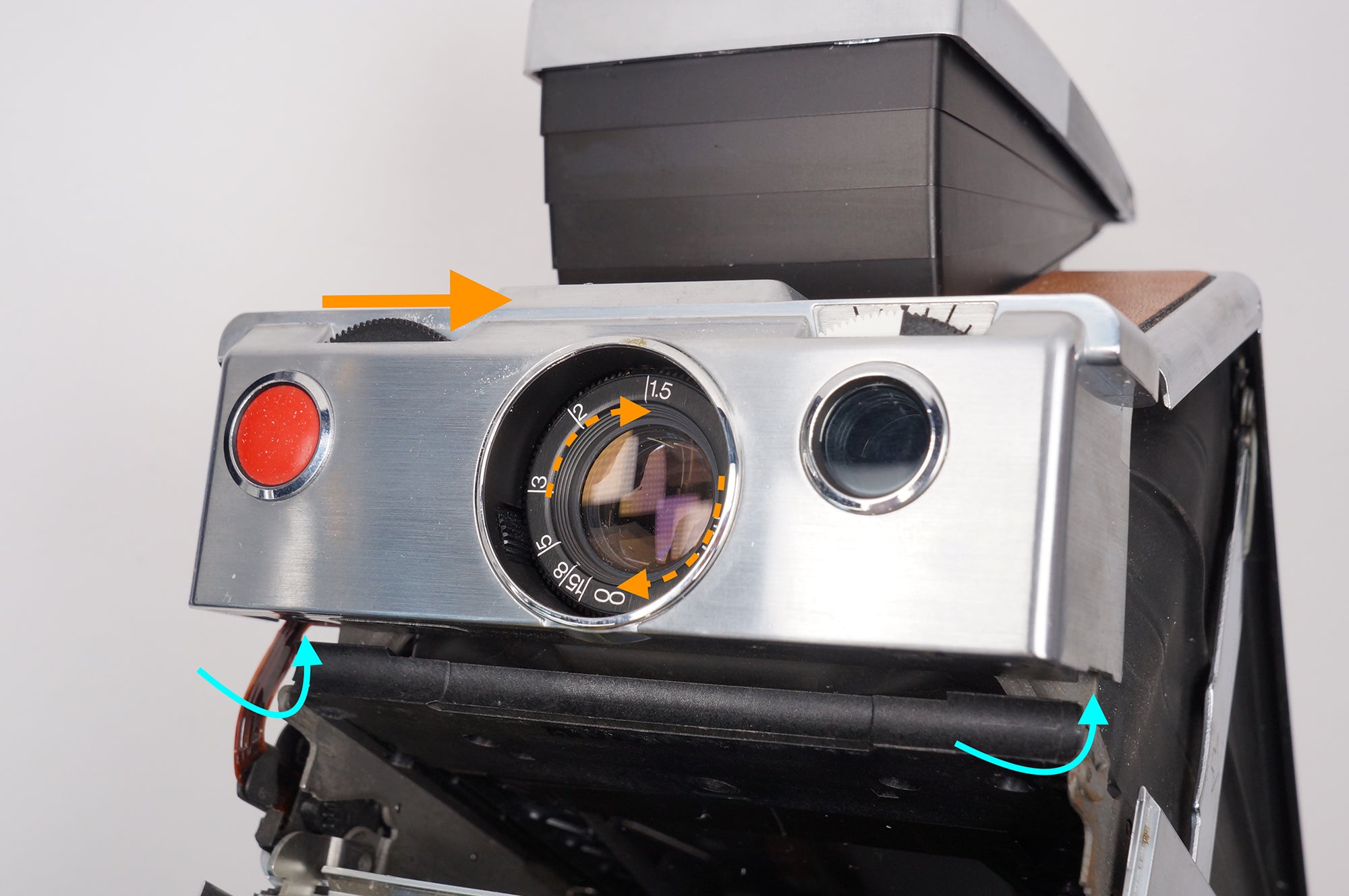
Ensure that the camera’s lens is focused to its infinity position (as far in as it will go). Failure to do this will result in damage to the camera.
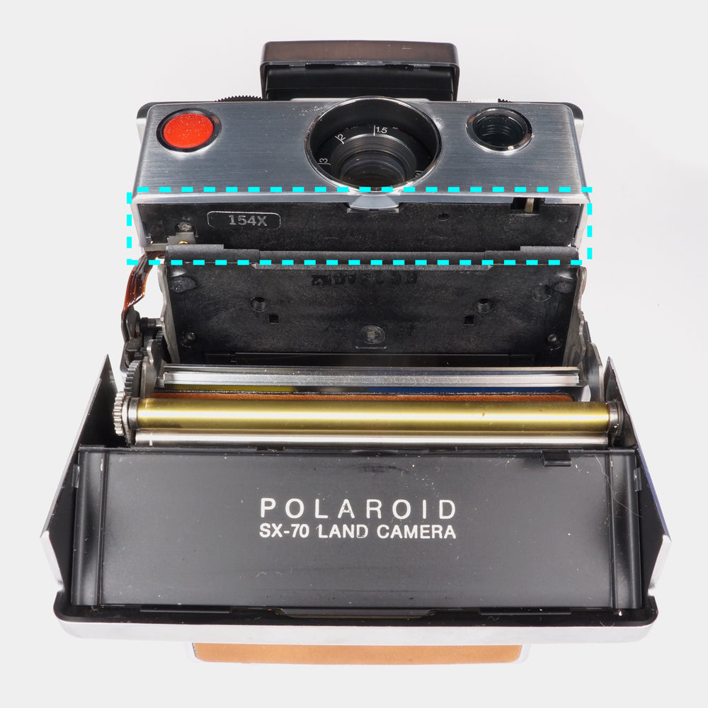
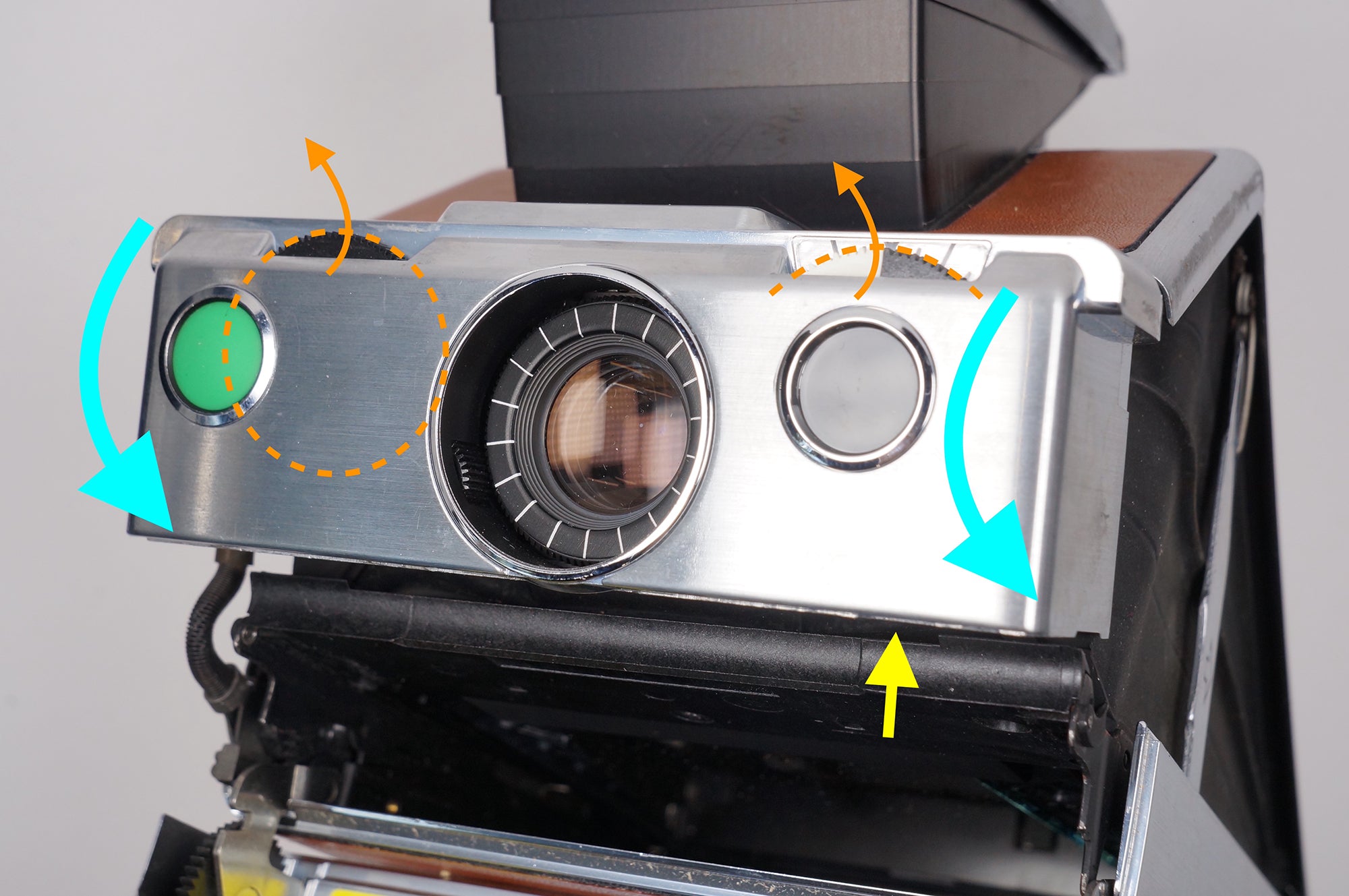
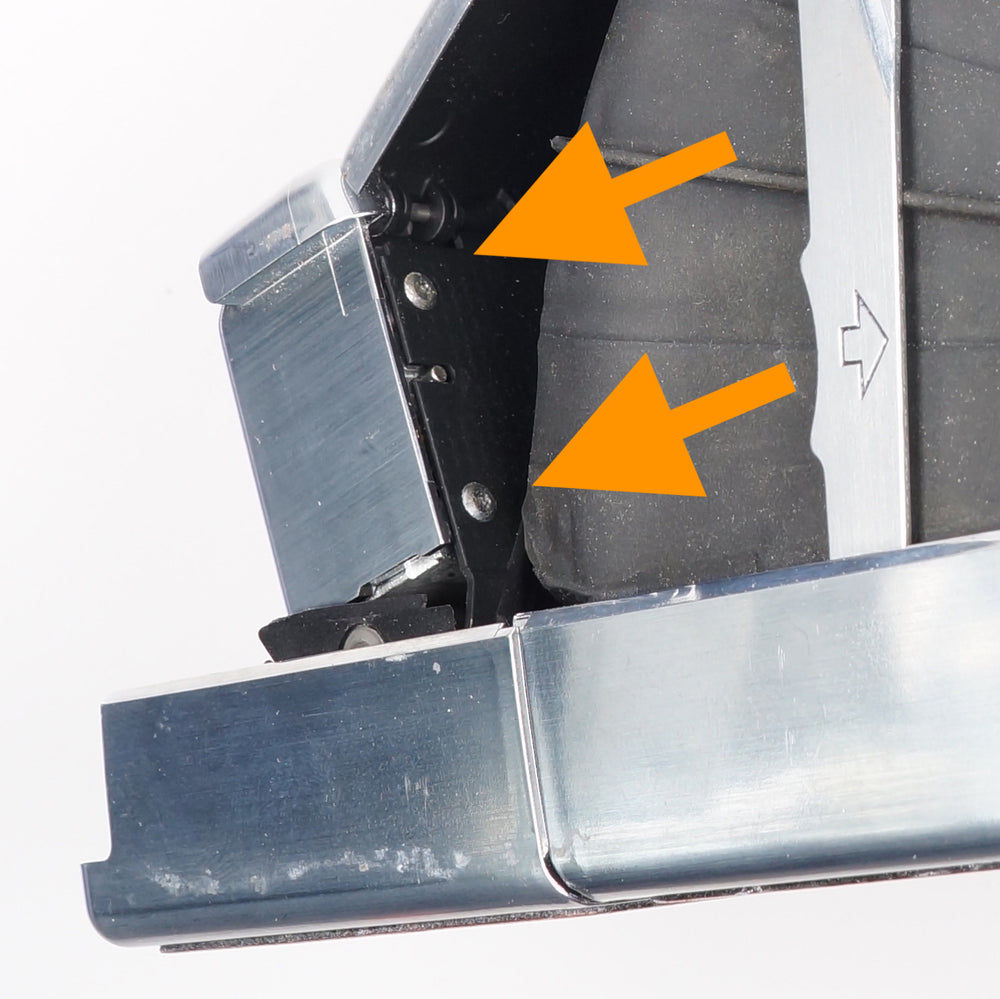
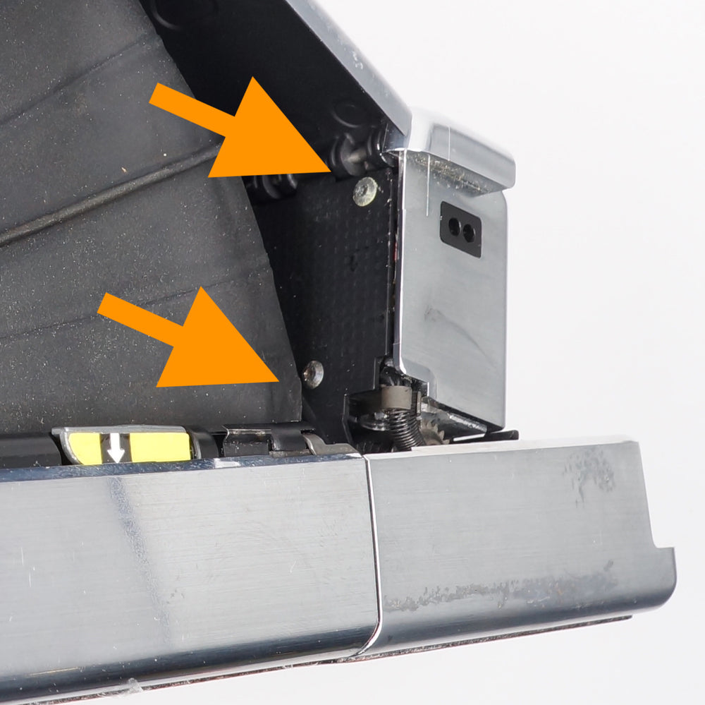
The shutter cover is held to the shutter crate by two tabs located at the bottom rear of the crate on each side of the shutter.
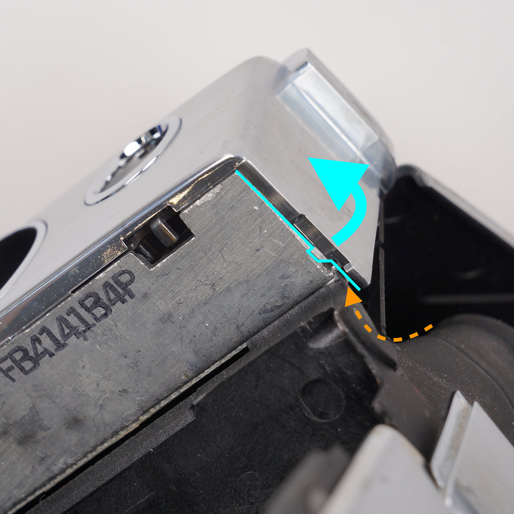
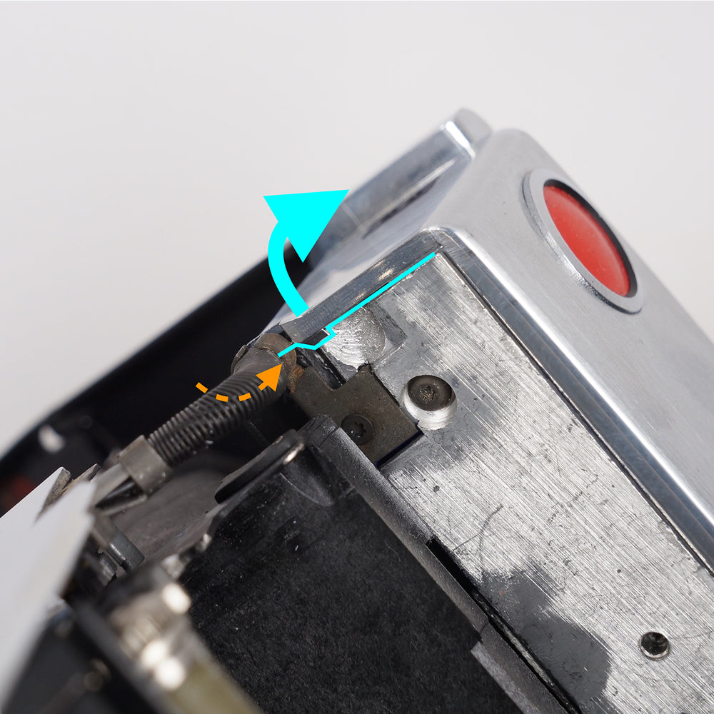
Using a flat-blade driver, gently pry the shutter cover away from the crate at the location of these two tabs. The goal is not to completely remove the cover at this step; rather, you are simply overcoming the tabs to allow the shutter cover to be removed.
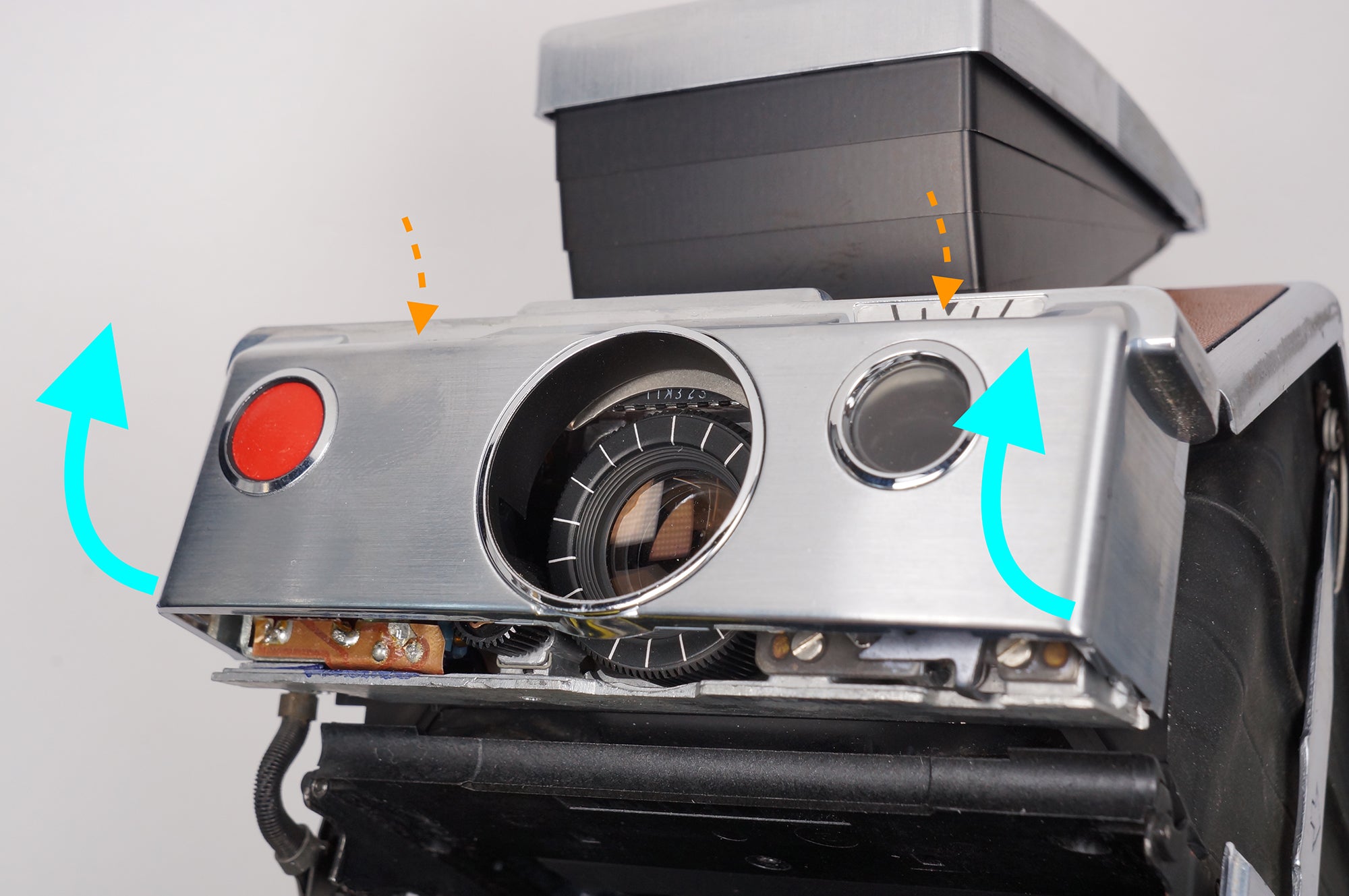
Once the tabs have been defeated, the shutter cover can be removed by rotating it upwards — the focus and L/D controls may have to be gently guided out of the openings in the shutter cover.
DISASSEMBLING THE SHUTTER BUTTON
With the shutter cover removed, you can now remove the original shutter button to replace it.
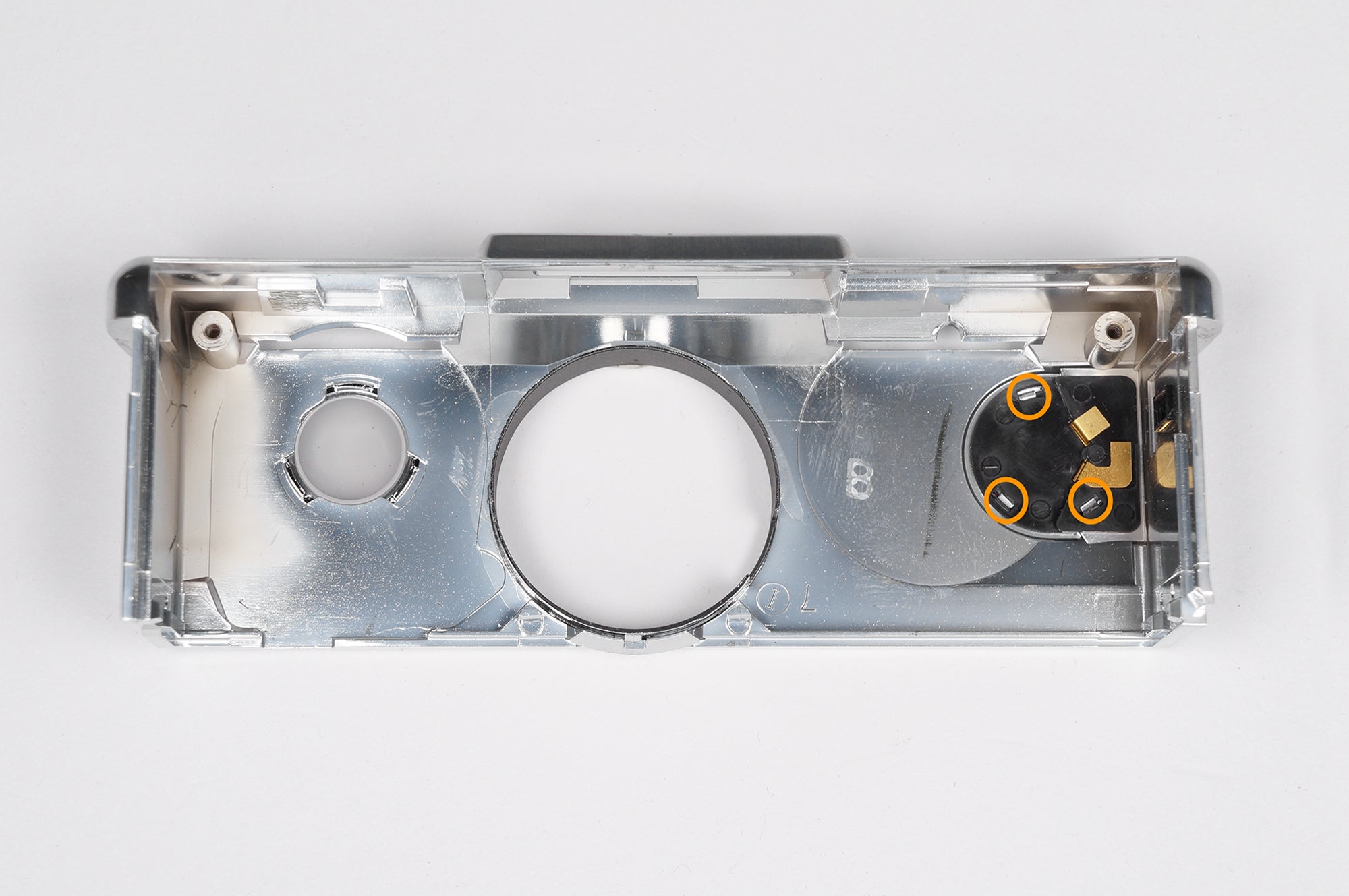
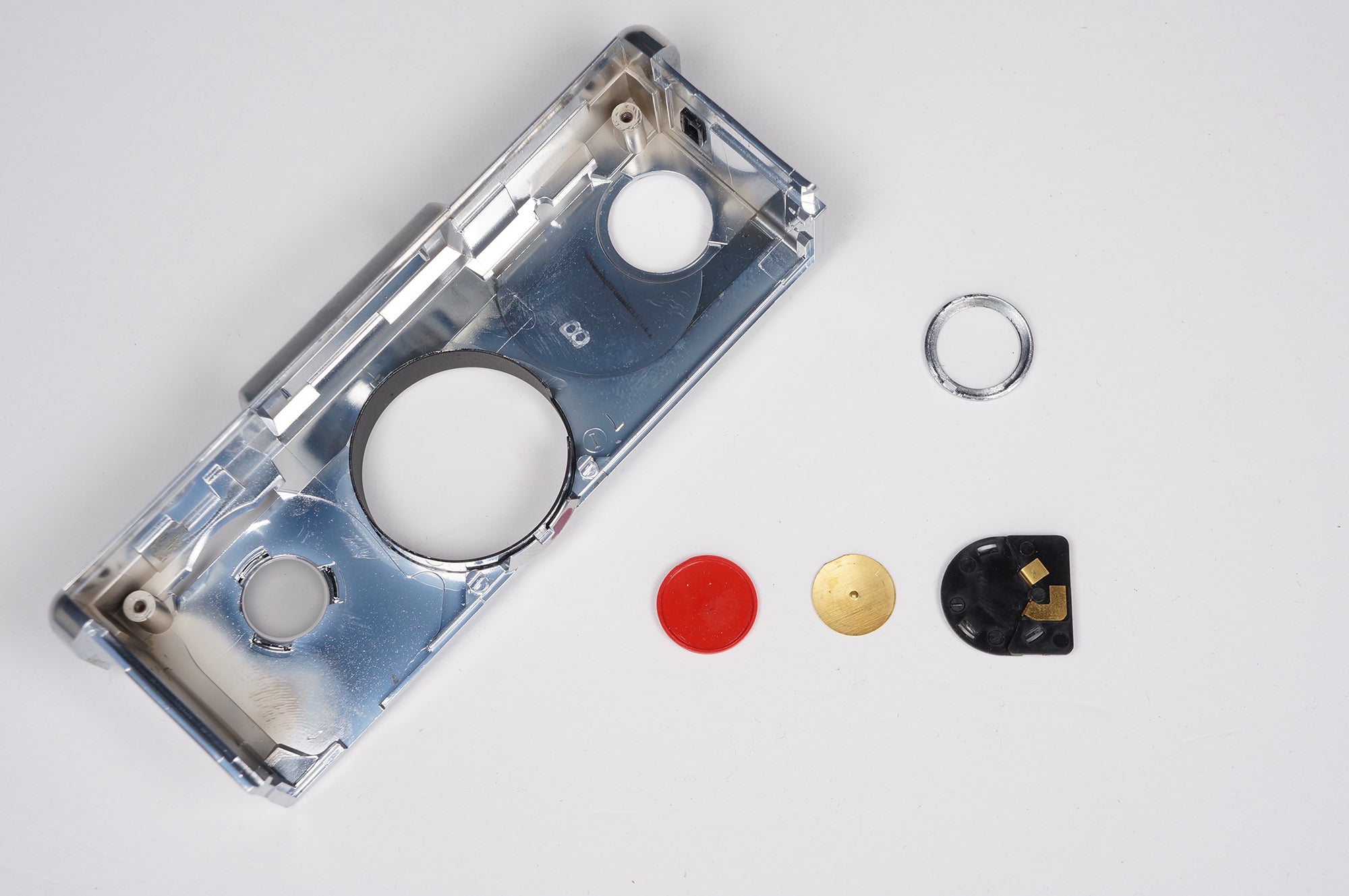
The button is held in place by the decorative bezel around it; the internals of the button disassemble to the rear/inside of the shutter cover. Place the shutter cover face down on the table — this will prevent the decorative retaining bezel from falling loose.
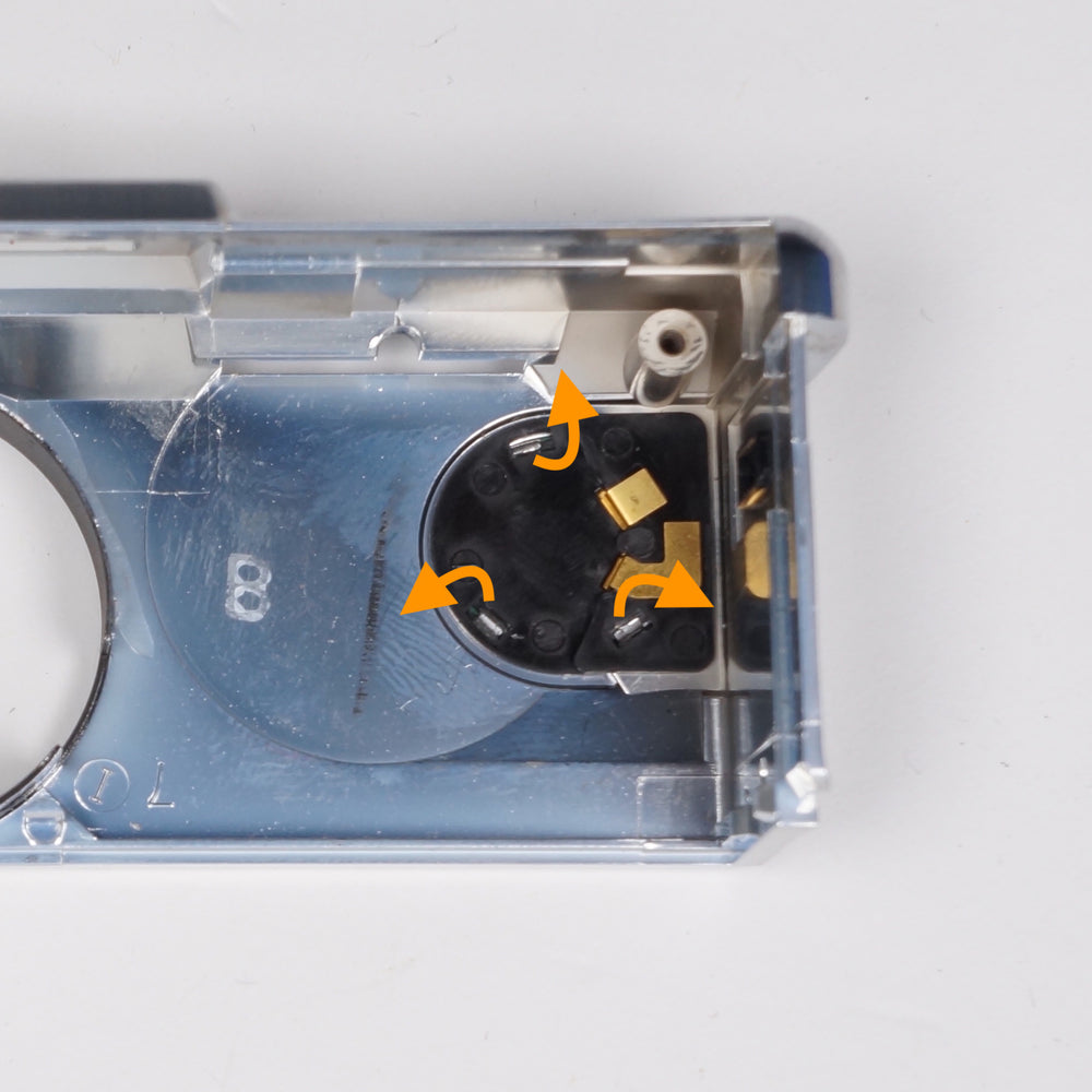
Using your flat-blade driver, gently pry up the three retaining tabs on the bezel. Be careful to not over-stress these tabs; if they break, the bezel must be replaced.
Once the three tabs have been straightened, the shutter cover button contacts can be lifted out.
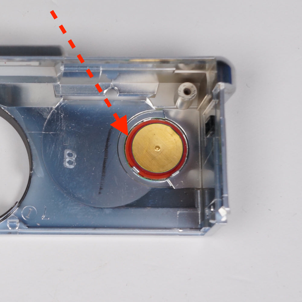
Under the shutter cover contacts is a small, convex metallic disc*. This is the part of the shutter button that produces the tactile “click” when you press it - the convex side should face downward when properly reassembled.
*The shutter cover button contacts of the Sonar, SLR 680, and Polaroid 690 do not have a separate convex disc; it is instead integral to the shutter cover button contacts.
With those parts removed, the old shutter button can now be removed.
REASSEMBLING THE SHUTTER BUTTON
The steps to reassemble the shutter button are simply the reverse of the disassembly instructions.
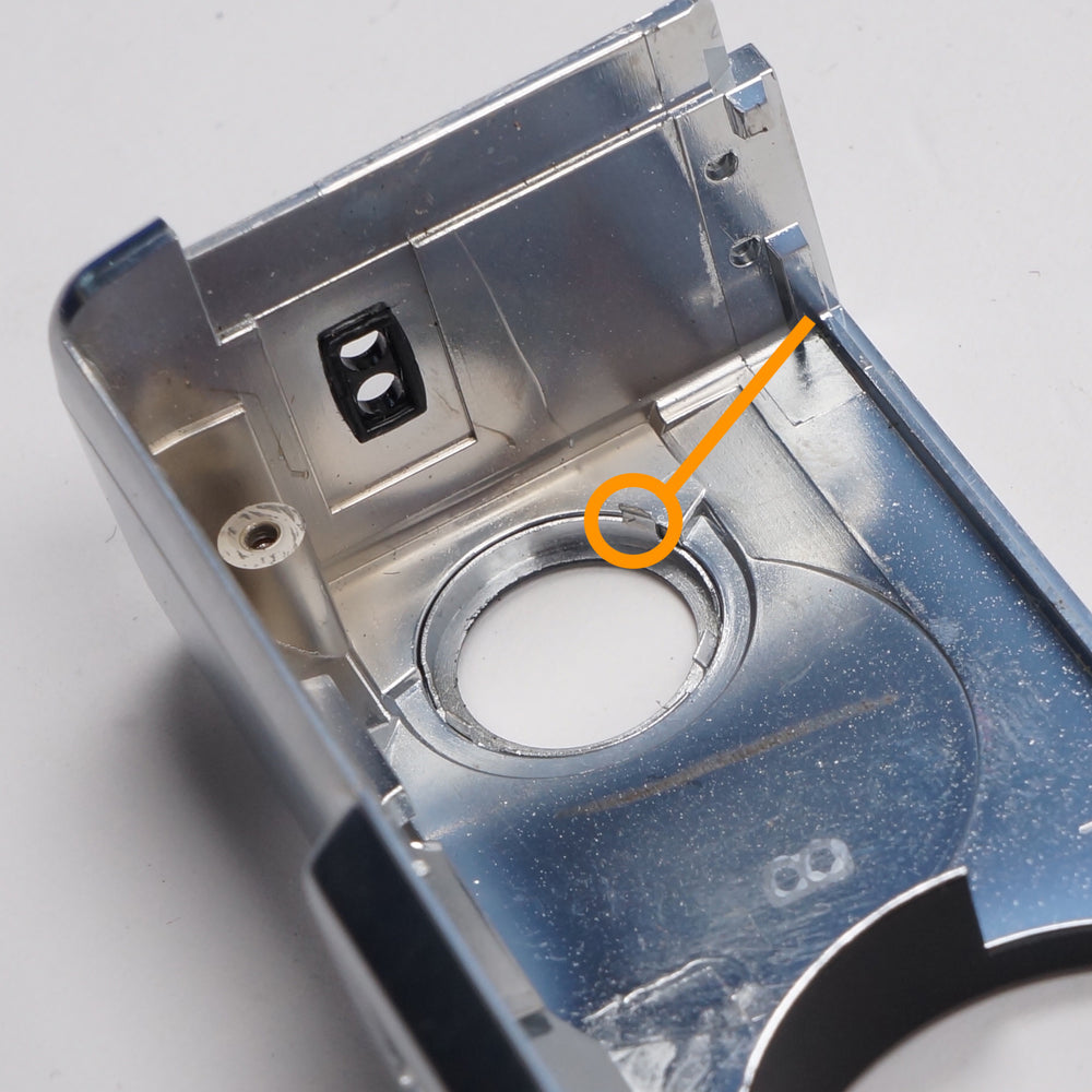
In theory, you should not need to remove the decorative bezel to switch out the button. However, if you do, note the correct orientation of the decorative retaining bezel — it has three tabs, one of which is longer than the others. This longer tab is oriented towards the bottom corner of the shutter cover. On later models of shutter cover, there are three positioning notches in the shutter cover itself — on earlier cameras, such as the pictured example, the orientation of this bezel must be done by eye.
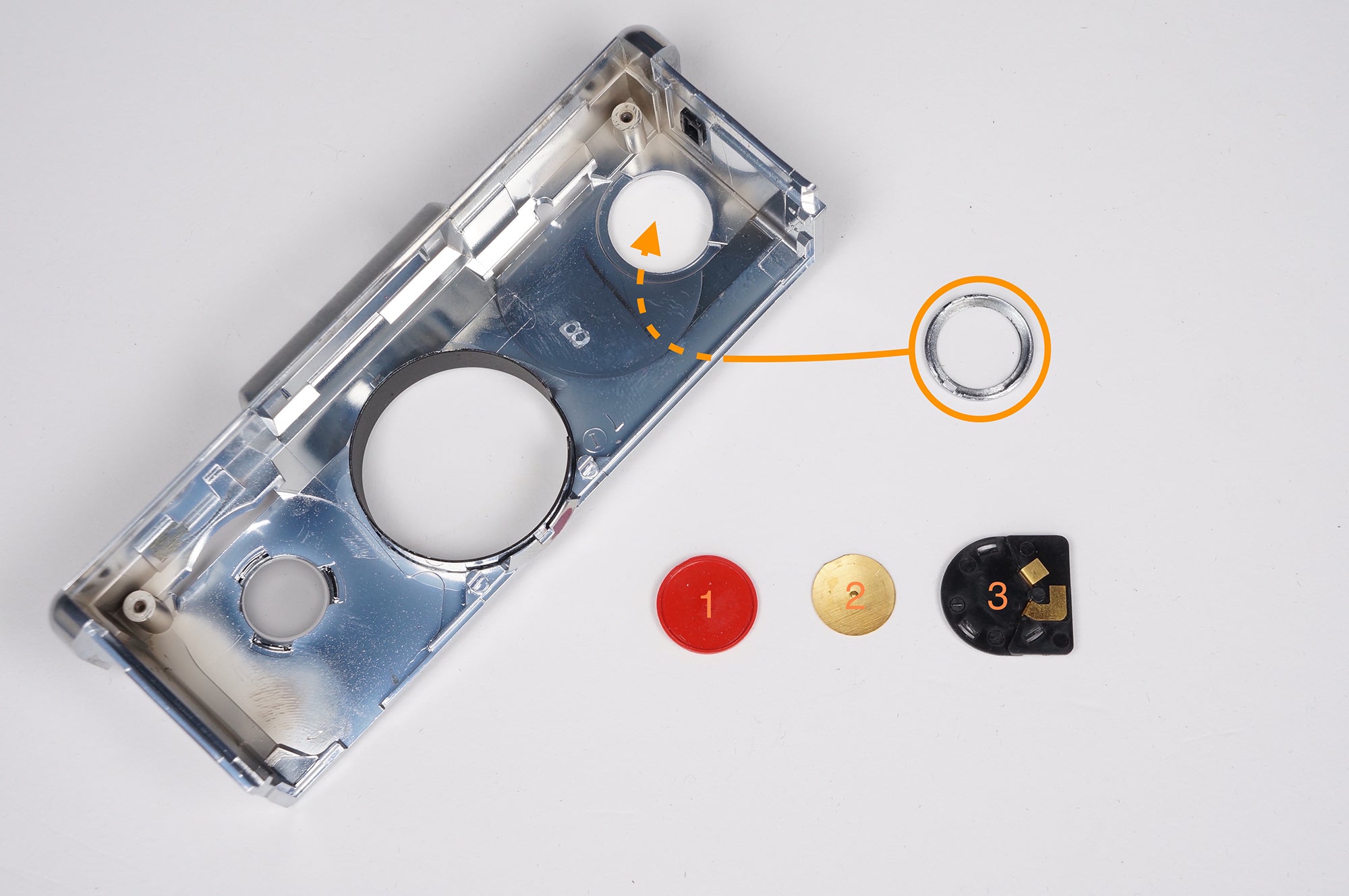
With the bezel in place, add the remaining pieces in the following order:
- Your new shutter button
- The convex metallic disc
- The shutter cover contacts
REINSTALLING THE SHUTTER COVER
Reassembly is the reverse of the disassembly procedure.
Place the shutter cover over the shutter crate. While pressing it back into position, be sure to guide the focus and L/D control dials into their respective openings in the shutter cover.
Once the shutter cover is almost fully seated, ensure that the L/D resetting link (located on the L/D control assembly) is not caught between the shutter cover and shutter crate.
You can then firmly press the shutter cover to completely seat it. You will probably hear it click into place - you can also visually confirm that the two shutter cover tabs have reseated on the shutter crate.
ADDITIONAL DISASSEMBLY (OLDER MODELS ONLY)
Some early cameras — recognized by the silver/aluminum shutter crates — have two additional fasteners that secure the shutter cover to the shutter crate. These fasteners can only be accessed by removing the entire shutter assembly from the shutter hinge plate. For this task, you will need a Torx 4 (T4) screwdriver. These can sometimes be found in sets sold at your local hardware store, but you may have to source them online. We recommend Wiha or Moody tool versions of these drivers.
Four T4 fasteners secure the shutter assembly to the shutter hinge plate. When removing these fasteners, take care to not mar the screw heads, shutter hinge plate, or damage the camera’s bellows.
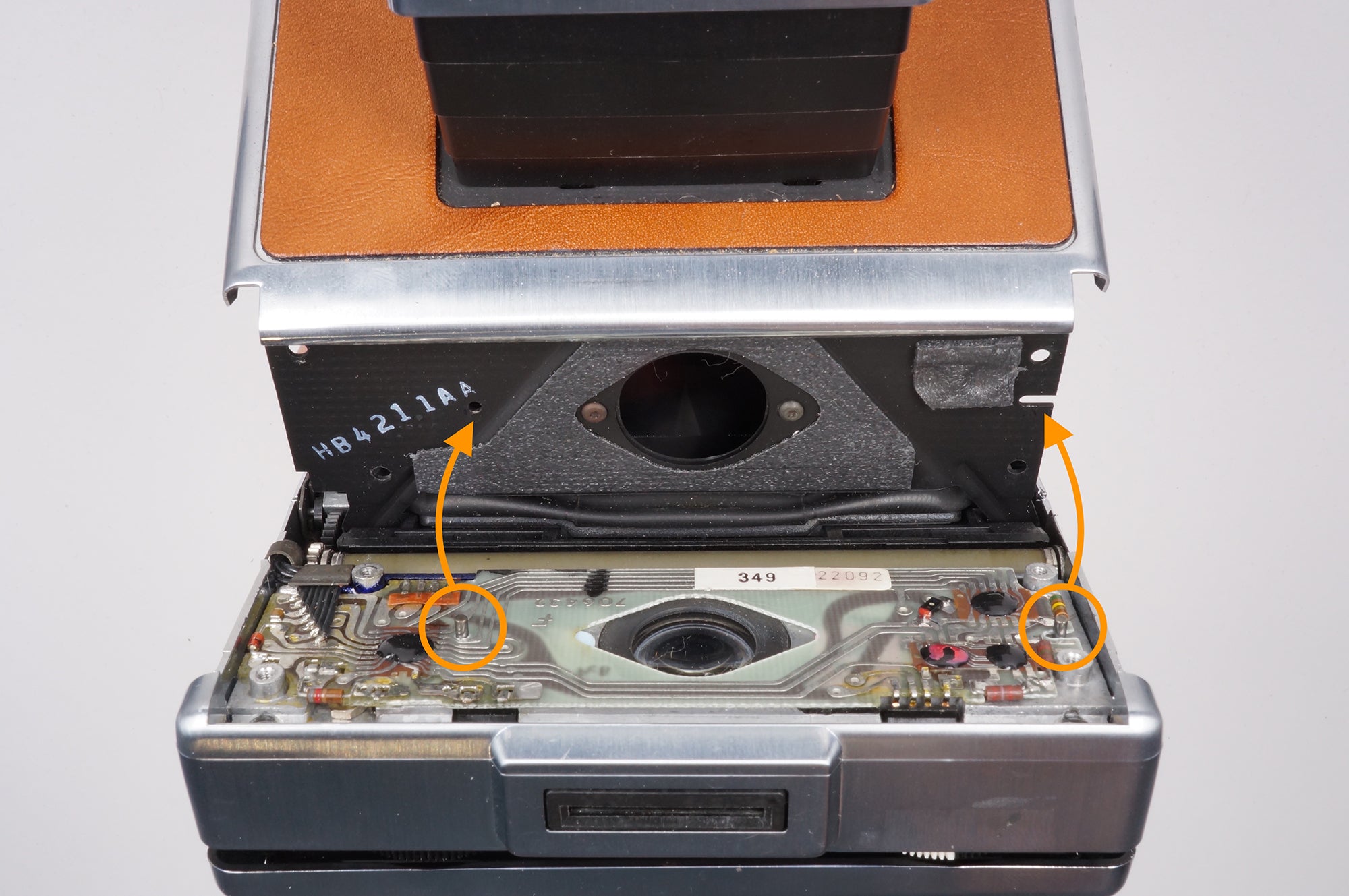
With those four fasteners removed, the shutter assembly can be gently pulled away from the shutter hinge plate.
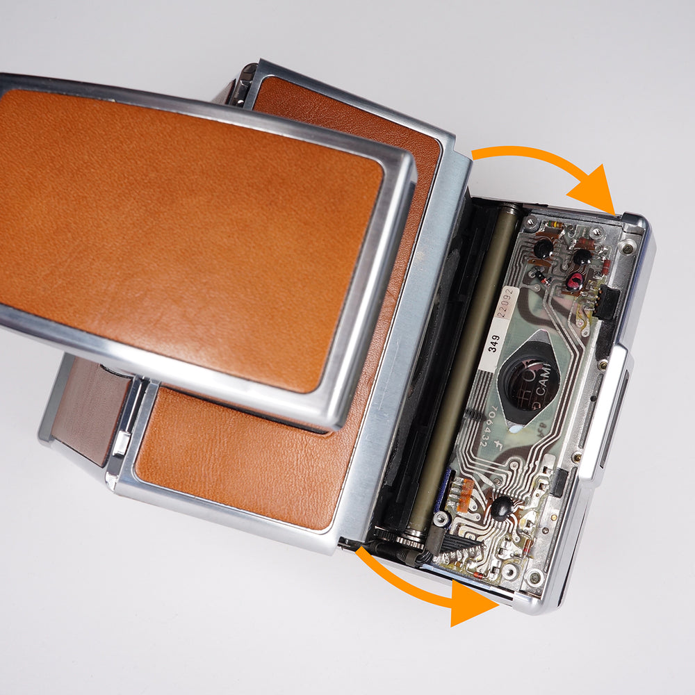
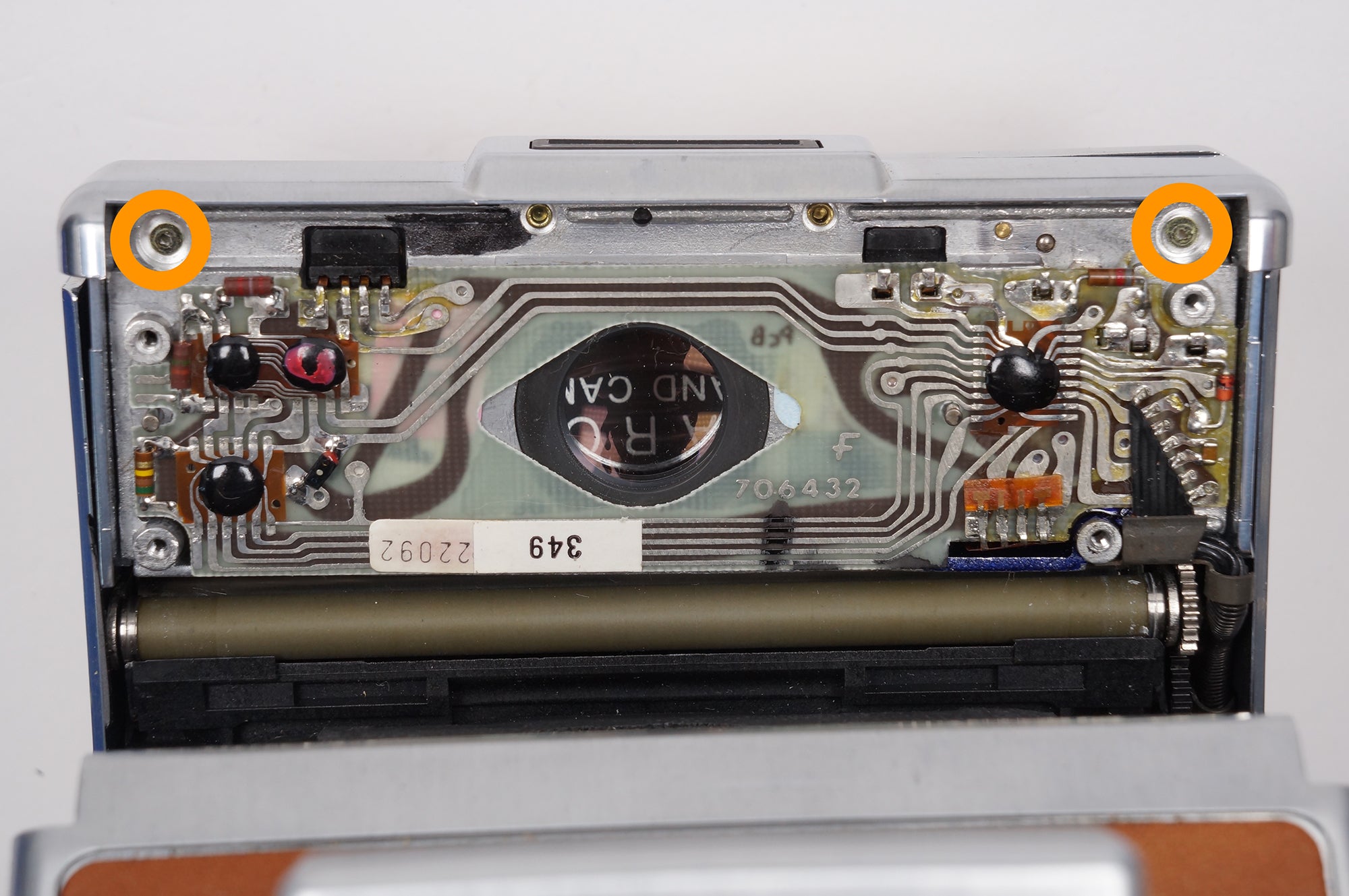
In the upper corners above the ECM, two additional T4 fasters can be seen. Remove these fasteners - the shutter button replacement can now follow the basic procedure steps.
Please note that the camera’s electronic control module (ECM) is now exposed, and care should be taken to ensure that no damage can occur to this often delicate circuit board. This is the camera’s “brain”, after all.
When remounting the shutter assembly to the shutter hinge plate, ensure that the two positioning posts are correctly aligned with the corresponding openings in the shutter hinge place.
While not strictly necessary, it is advisable to to replace the two fasteners that secure the shutter cover to the shutter crate. These fasteners ensure that the shutter cover is precisely positioned on the crate.
SONAR EQUIPPED MODELS
⚠ SAFETY WARNING
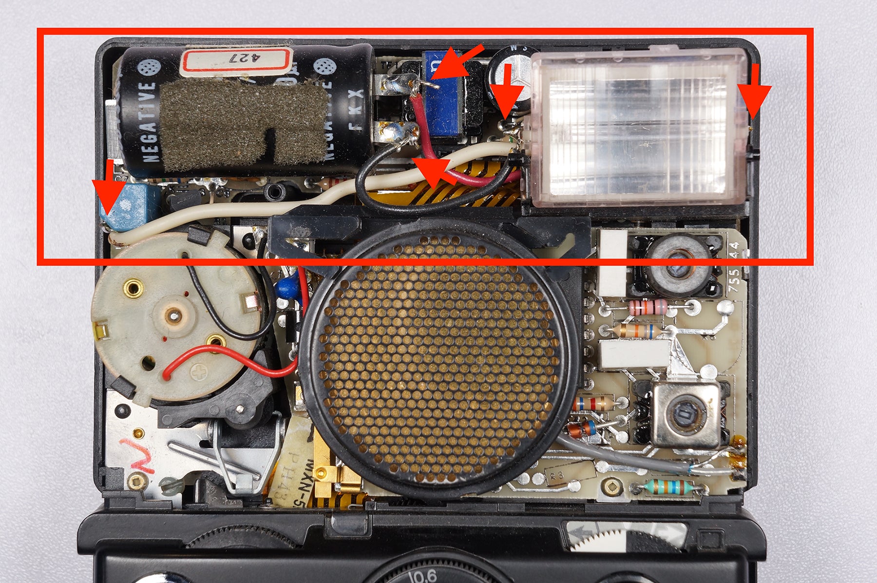
If you are working on an SLR 680 or Polaroid 690, please be aware that there is a high voltage shock hazard owing to the electronic flash circuitry that will be exposed once the upper cover is removed. We can’t tell you not to work on these cameras, but we must emphasize the potential danger inherent to working with high-voltage electronics and you do so at your own risk.
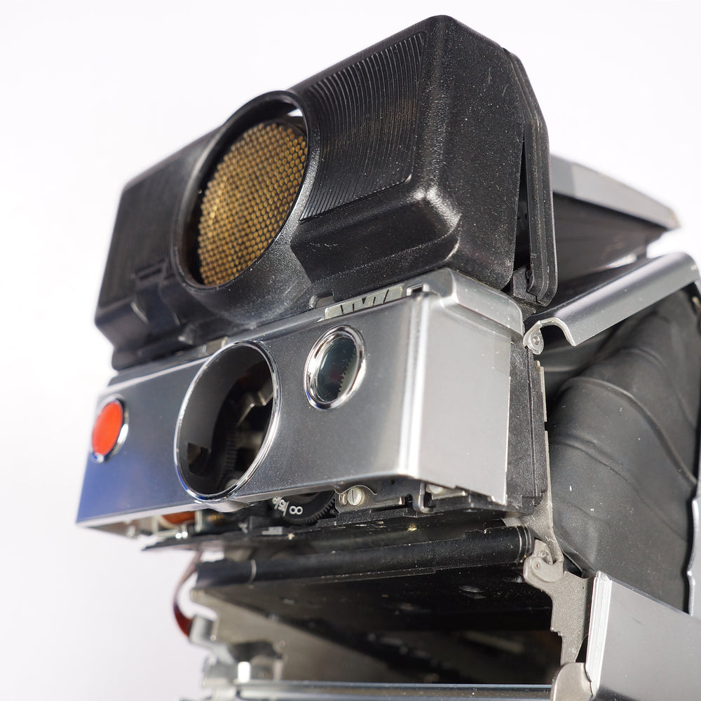
Additional steps and cautions should be when removing the shutter cover of autofocus-equipped cameras (Sonar, SLR 680, Polaroid 690). While the illustrated example is an SLR 680, the same general principles apply to Sonar cameras.
If your camera is a Sonar without a built-in flash, you can skip this next section.
SLR 680/690 EXTRA DISASSEMBLY
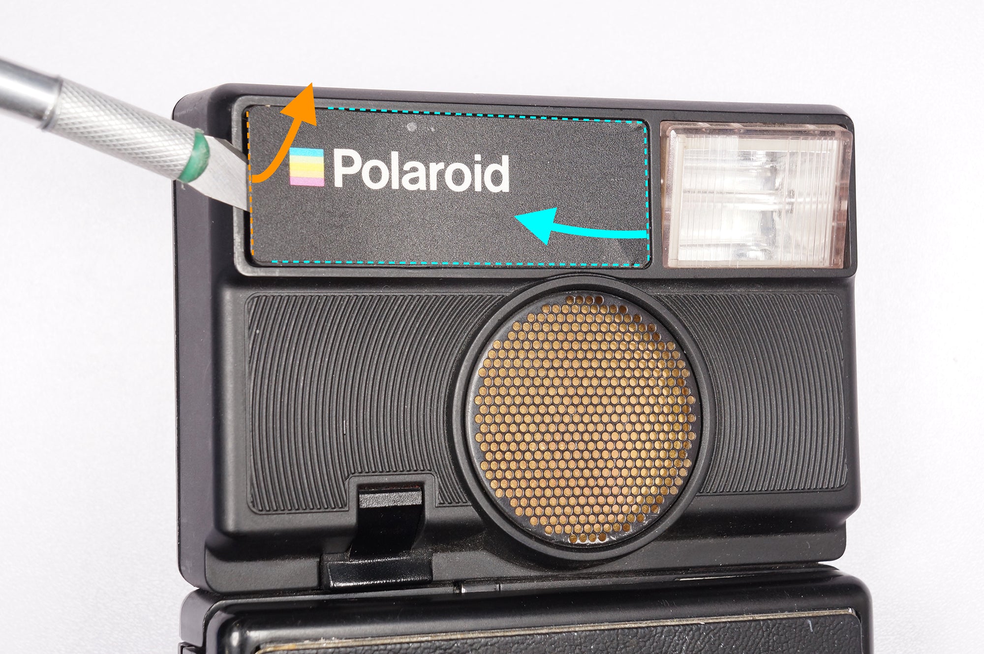
On the SLR 680 or Polaroid 690, a fastener is located underneath the name plate located at the top/front of the sonar/strobe cover. To access and remove this fastener, you will need a thin/flat implement - a carefully handled Exacto knife in the illustrated example.
Insert the thin/flat implement between the edge of the name plate and the upper cover to flex the plate upward by about 1mm. While that edge is listed, press the entire nameplate outboard until it comes free.
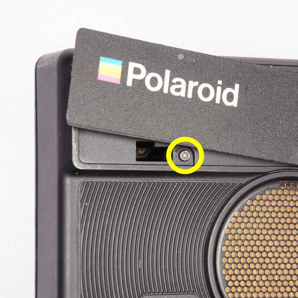
The fastener located under the name plate has a proprietary square drive type used only by Polaroid — this was done to prevent tampering by unauthorized individuals. There is no commercially available screwdriver available for purchase, so removing this fastener will require you to either:
-
Fabricate/source your own square driver, as we have done.
-
Cut a small slot in the head of the screw in order to extract it with your flat-blade screwdriver.
DISASSEMBLY FOR ALL SONAR MODELS
If you skipped the SLR 680/690 section, join back up here!
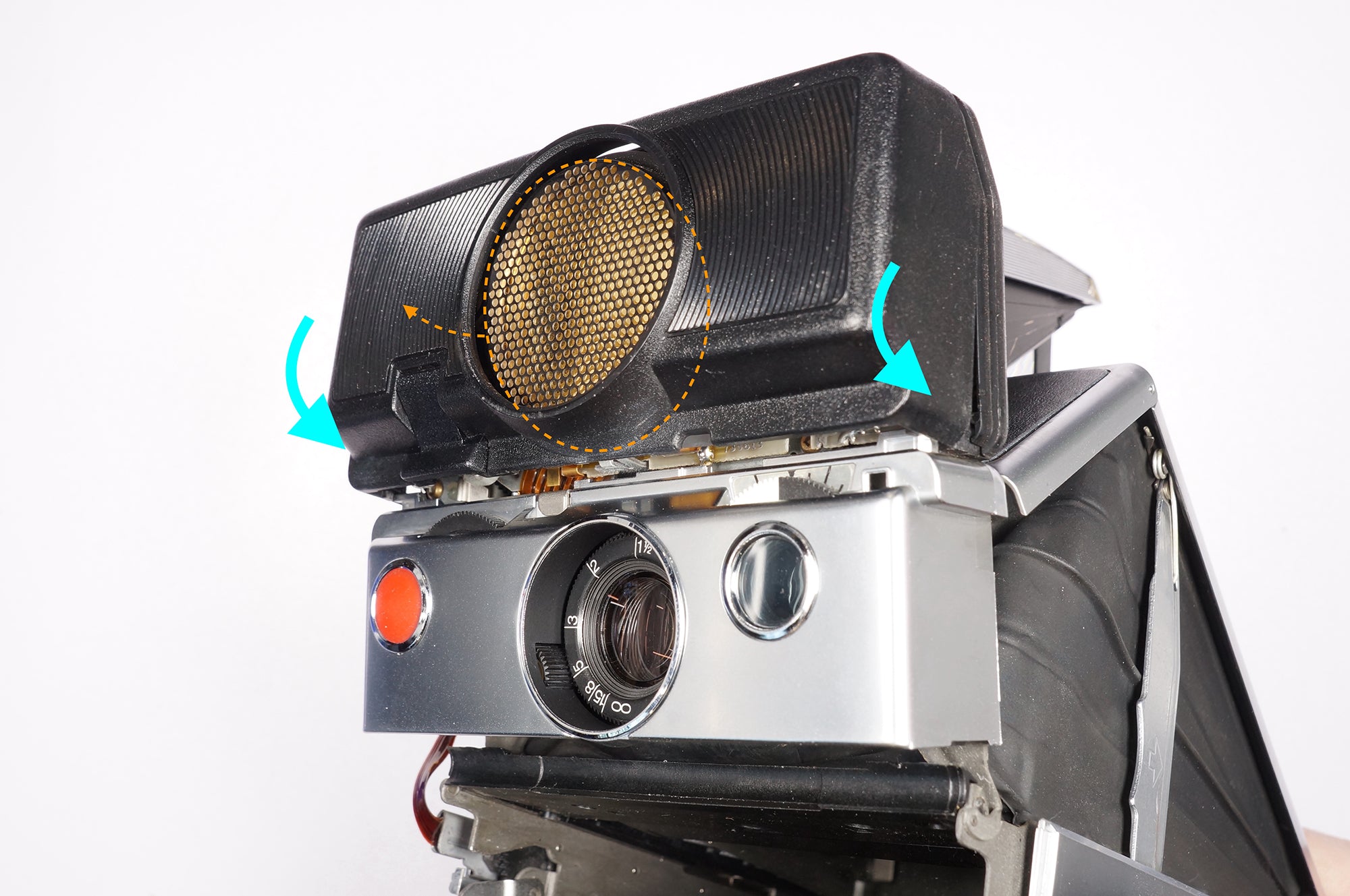
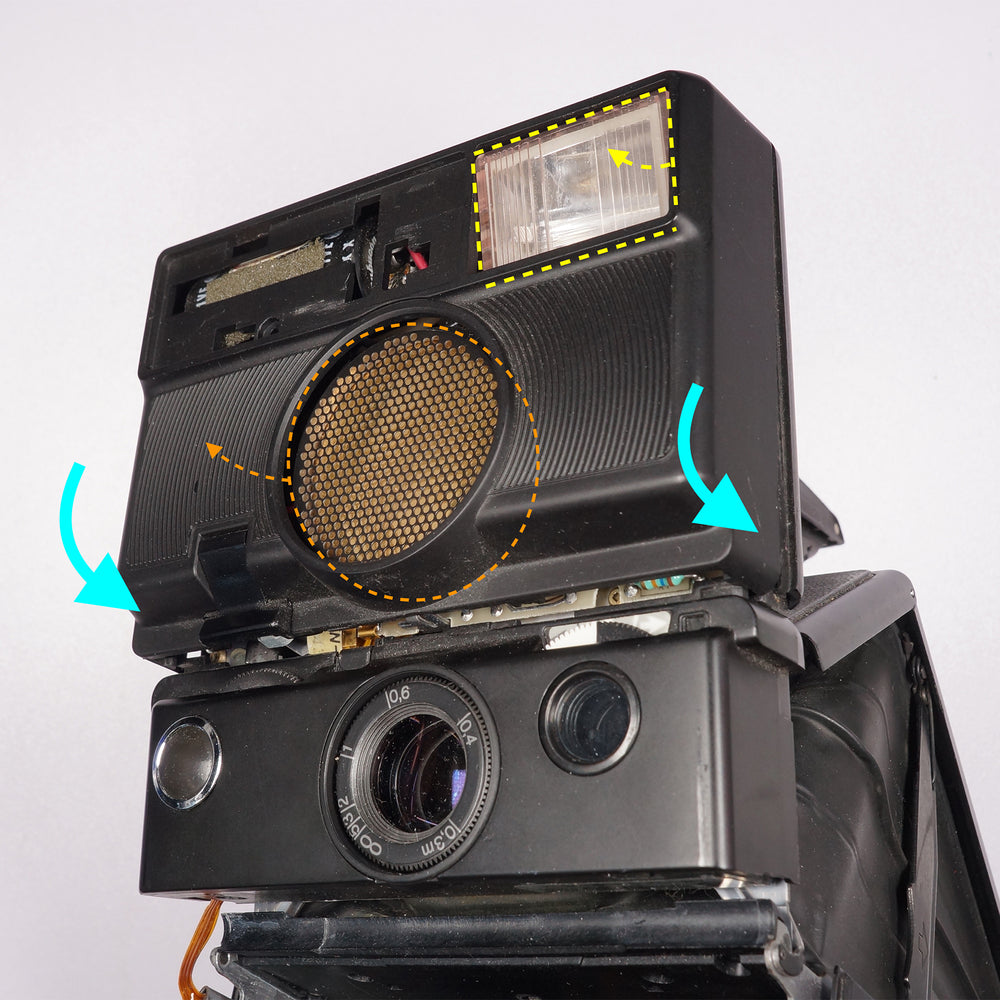
Remove the shutter cover and Sonar front cover together in the same manner described in the basic procedure. We recommend removing the two parts from the camera together so as to prevent breaking the delicate tabs that secure the Sonar cover to the shutter cover or otherwise marring the cosmetic finish.
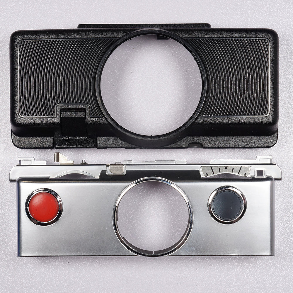
Once the shutter cover and Sonar front cover are separated from the shutter assembly, you can then safely separate them from each other.
From here, follow the same general procedure with regard to replacing the shutter button.
REASSEMBLY NOTES
Reinstall the shutter cover in the same manner as described in the basic procedure.
If you have a Sonar camera, you can then install its front cover using the same general technique.
SLR 680/690 REASSEMBLY NOTES
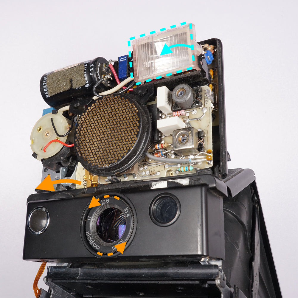
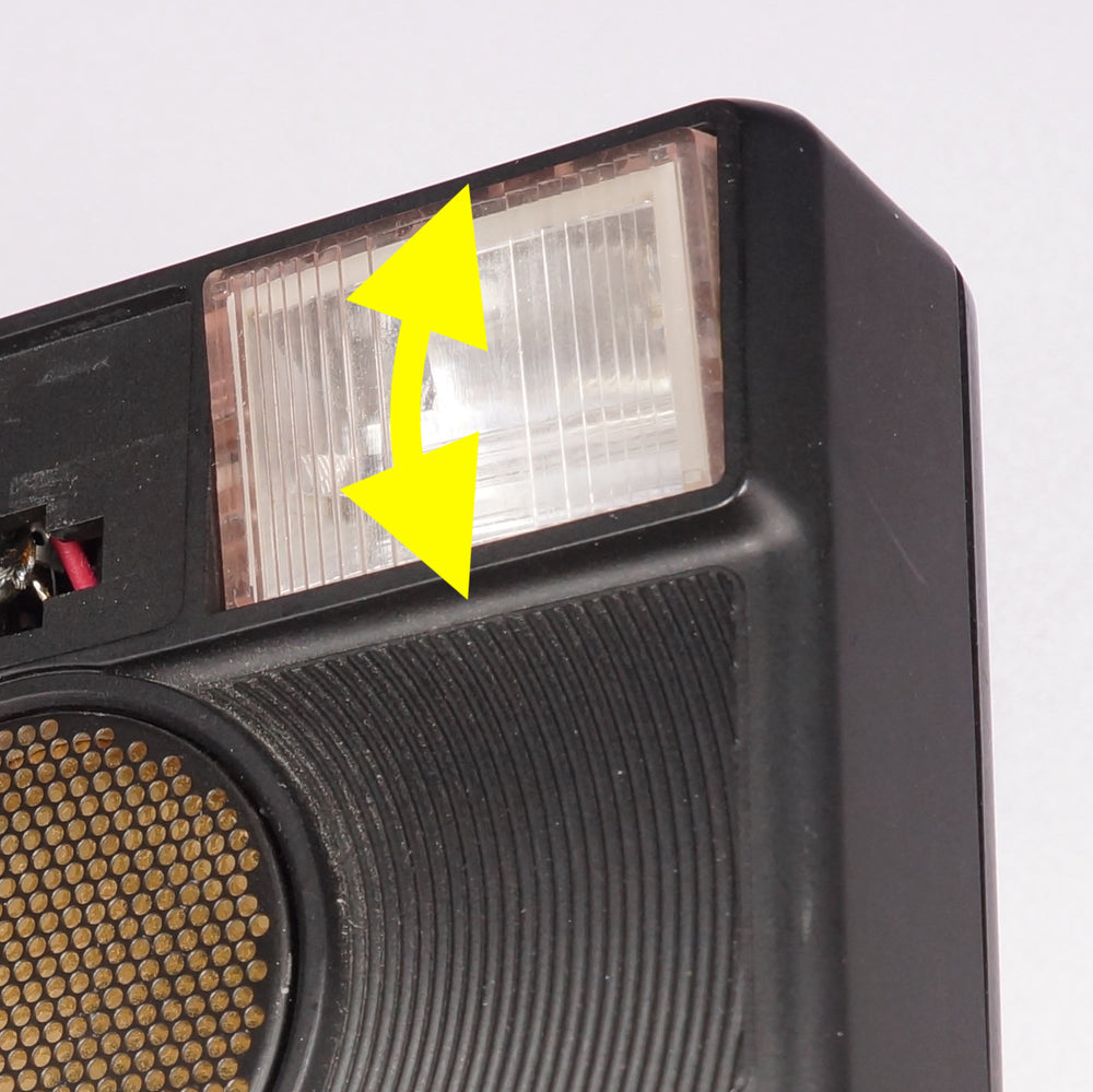
If you have an SLR 680 or 690, you must now manually focus the lens to its close-focus position. This will tilt the flash lamp downward — if you fail to follow this step, when the front sonar/strobe cover is reinstalled the lamp will not be able to tilt as designed. You can now install the sonar/strobe front cover.
Ensure that the flash lamp can move freely once the cover is fully and correctly seated.
We highly recommend reinstalling the fastener under the name plate.